Dimension
The dimensions of TE86 are shown below.
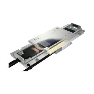
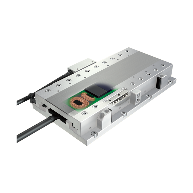
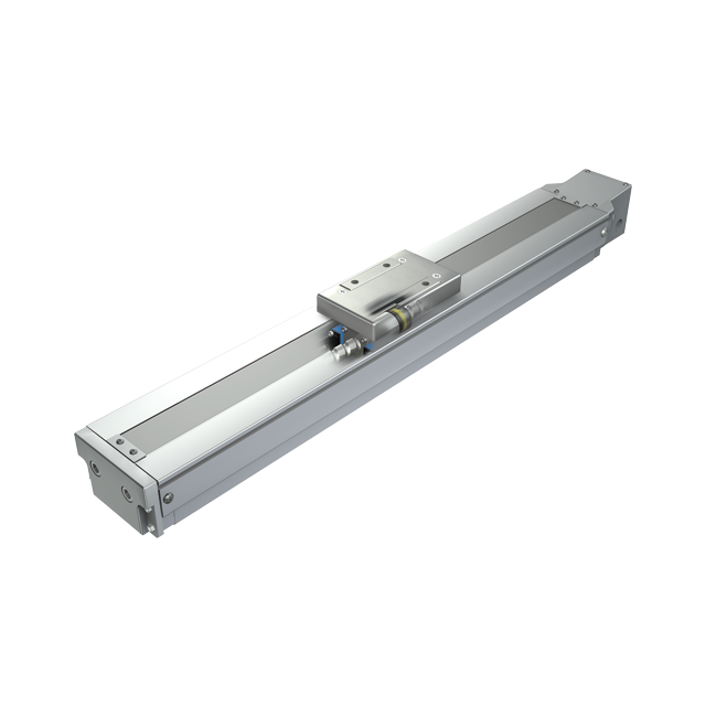
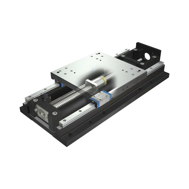
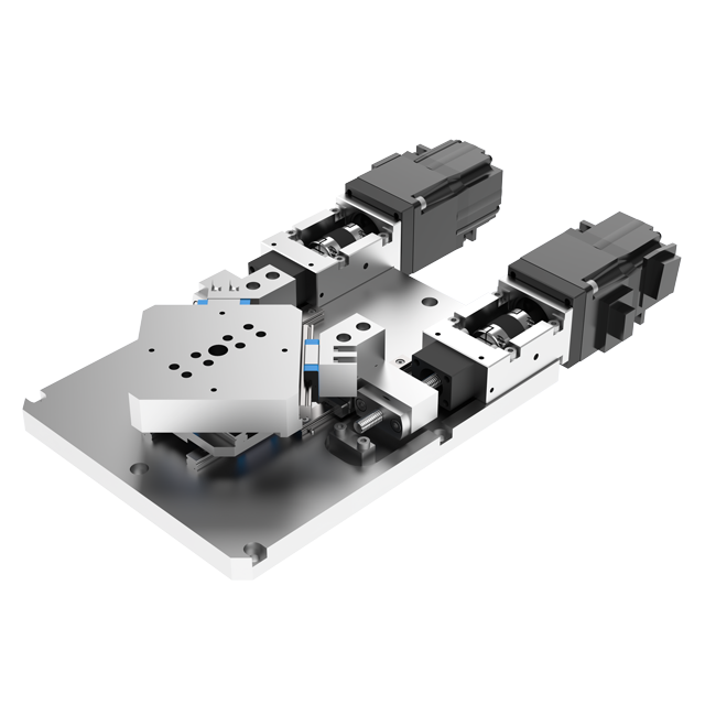
TE86BS(Motor inline specification)
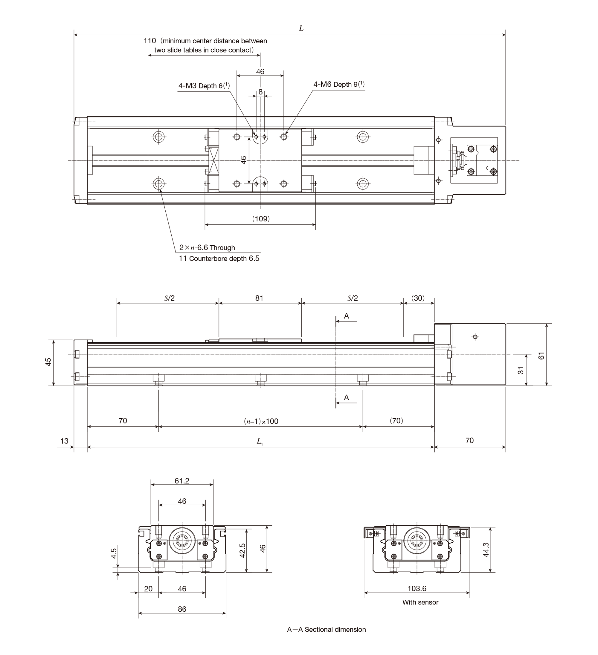
unit: mm
| Bed length L1 |
Overall length L |
Stroke length S(2) |
Mounting holes of bed n |
Mass(Ref.) Kg(3) |
|---|---|---|---|---|
| 340 | 423 | 200(90) | 3 | 3.1 |
| 440 | 523 | 300(190) | 4 | 3.7 |
| 540 | 623 | 400(290) | 5 | 4.2 |
| 640 | 723 | 500(390) | 6 | 4.7 |
| 740 | 823 | 600(490) | 7 | 5.2 |
| 840 | 923 | 700(590) | 8 | 5.7 |
| 940 | 1023 | 800(690) | 9 | 6.3 |
| Notes(1) | Too deep a fixing thread depth of the mounting bolt may affect the running performance of the slide table, so never insert a bolt longer than the depth of the tapped hole. |
| (2) | The value indicates the allowable stroke when limit sensors are mounted. The value in ( ) represents dimension for two slide tables in close contact. |
| (3) | The value shows the mass of the entire table with one slide table, and it is 0.3kg heavier with two slide tables. |
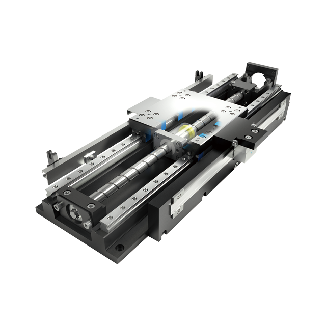
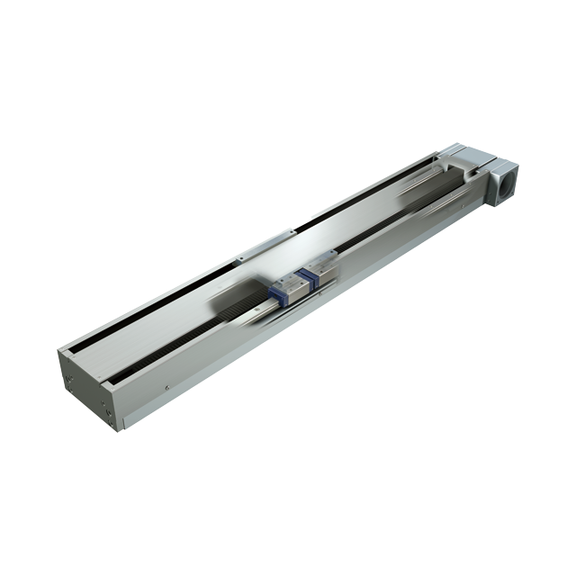
TE86BF(Motor inline specification)
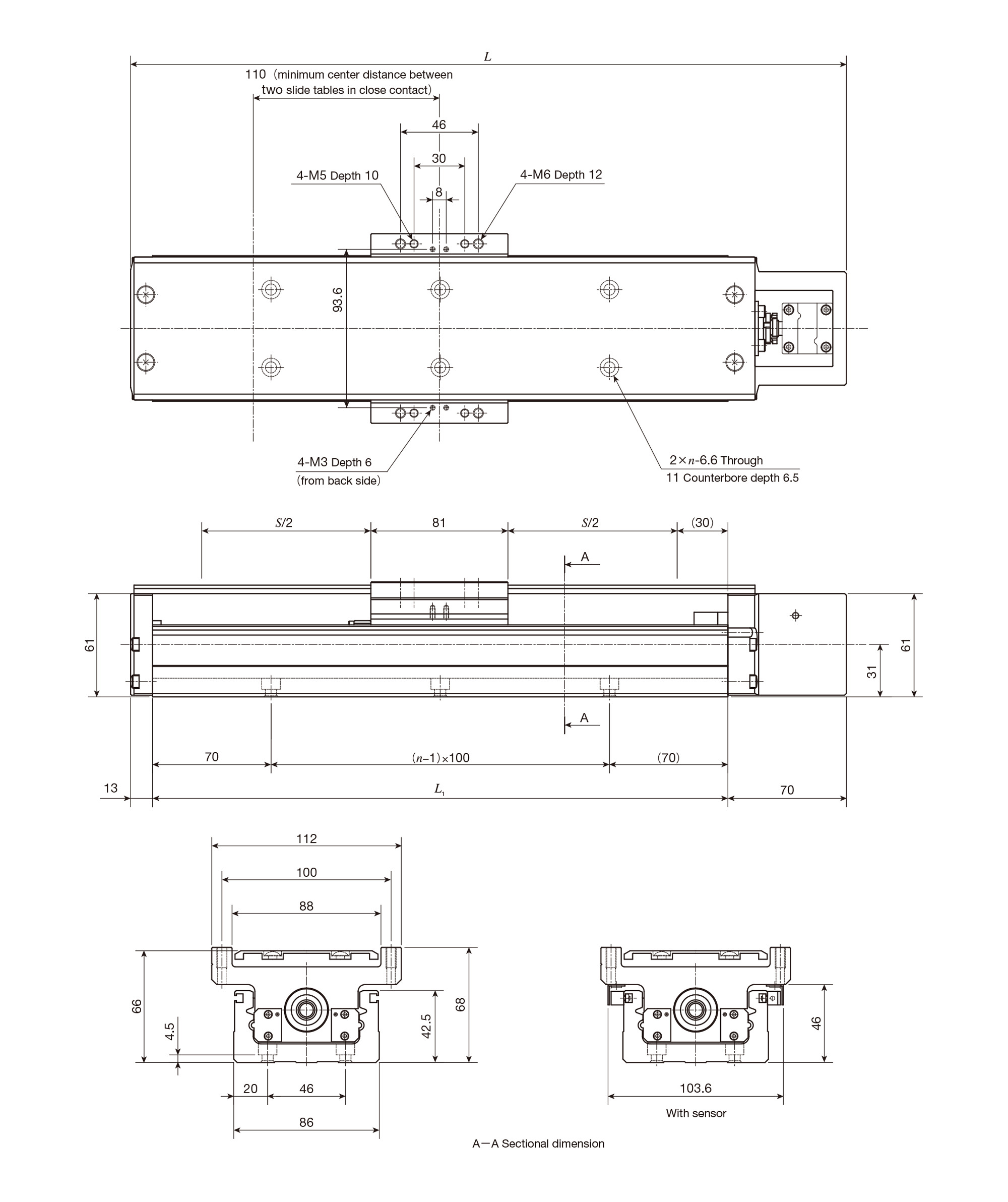
unit: mm
| Bed length L1 |
Overall length L |
Stroke length S(1) |
Mounting holes of bed n |
Mass(Ref.) Kg(2) |
|---|---|---|---|---|
| 340 | 423 | 200(90) | 3 | 3.7 |
| 440 | 523 | 300(190) | 4 | 4.3 |
| 540 | 623 | 400(290) | 5 | 4.9 |
| 640 | 723 | 500(390) | 6 | 5.5 |
| 740 | 823 | 600(490) | 7 | 6.1 |
| 840 | 923 | 700(590) | 8 | 6.7 |
| 940 | 1023 | 800(690) | 9 | 7.2 |
| Notes(1) | The value indicates the allowable stroke when limit sensors are mounted. The value in( ) represents dimension for two slide tables in close contact. |
| (2) | The value shows the mass of the entire table with one slide table, and it is 0.6kg heavier with two slide tables. |
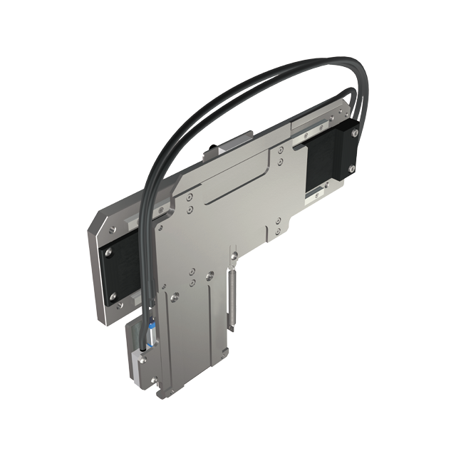
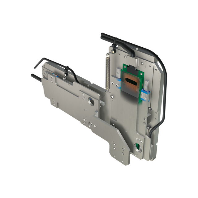
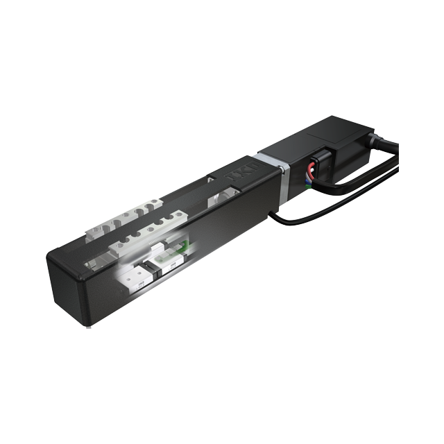
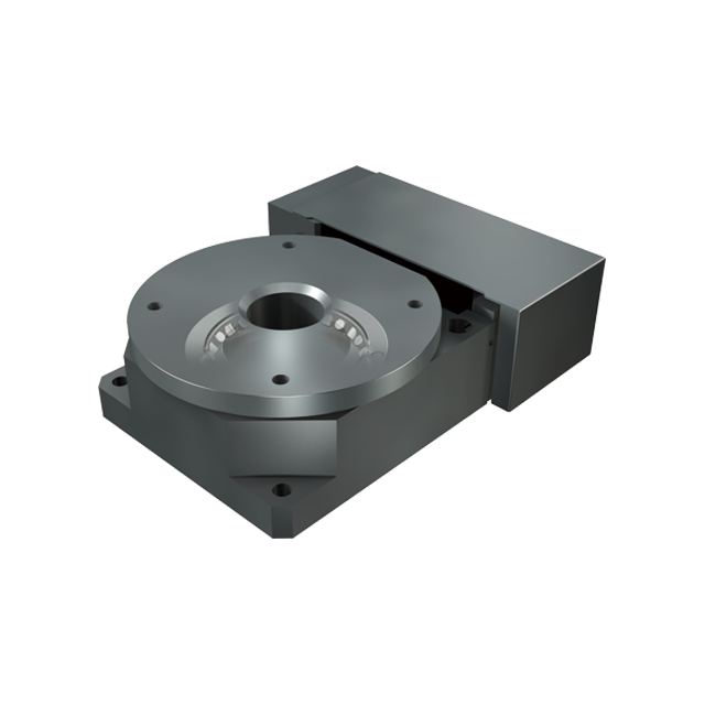
TE86BS(Motor folding back specification)
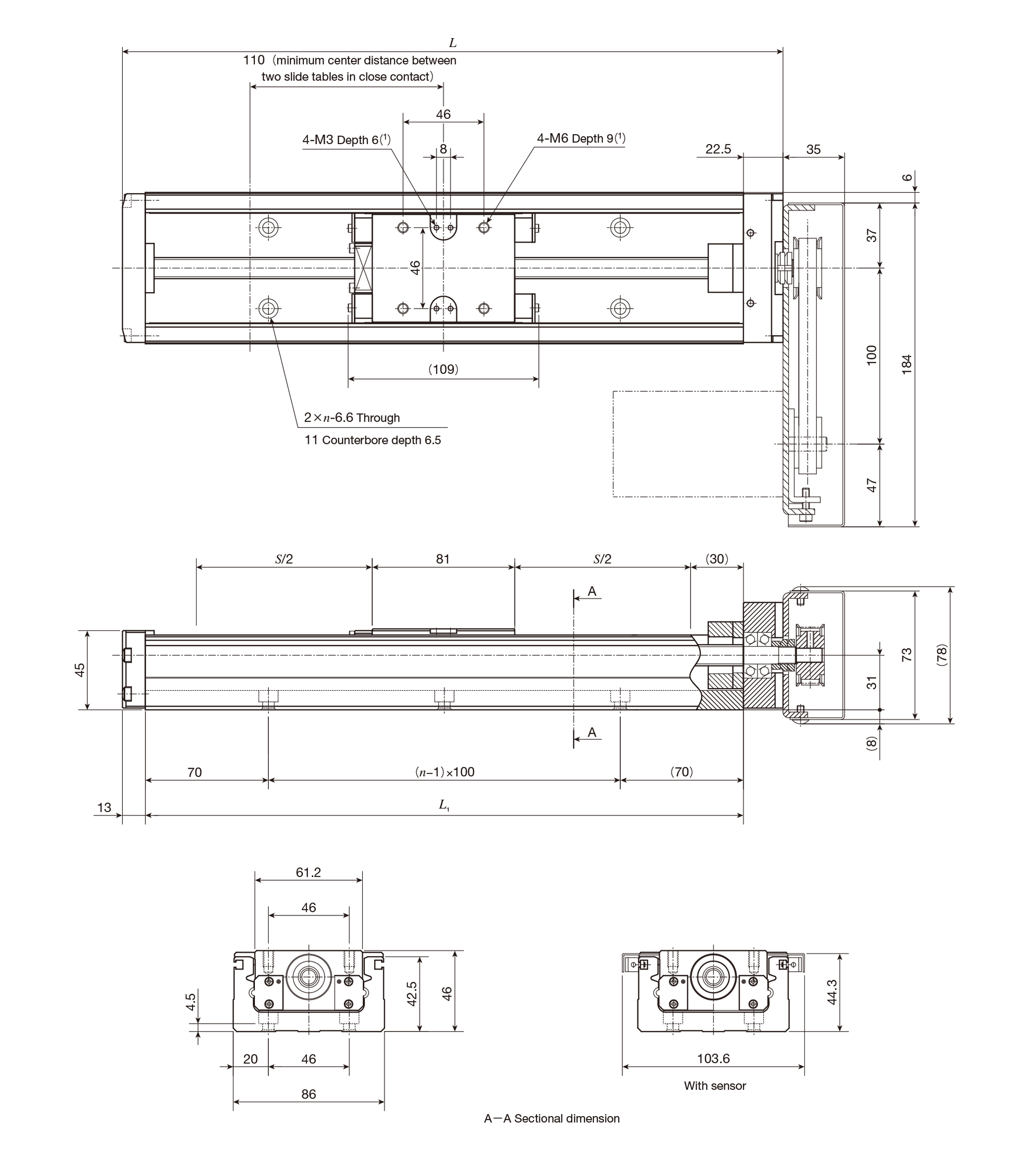
unit: mm
| Bed length L1 |
Overall length L |
Stroke length S(2) |
Mounting holes of bed n |
Mass(Ref.) Kg(3) |
|---|---|---|---|---|
| 340 | 375.5 | 200(90) | 3 | 4.0 |
| 440 | 475.5 | 300(190) | 4 | 4.6 |
| 540 | 575.5 | 400(290) | 5 | 5.1 |
| 640 | 675.5 | 500(390) | 6 | 5.6 |
| 740 | 775.5 | 600(490) | 7 | 6.1 |
| 840 | 875.5 | 700(590) | 8 | 6.6 |
| 940 | 975.5 | 800(690) | 9 | 7.2 |
| Notes(1) | Too deep a fixing thread depth of the mounting bolt may affect the running performance of the slide table, so never insert a bolt longer than the depth of the tapped hole. |
| (2) | The value indicates the allowable stroke when limit sensors are mounted. The value in ( ) represents dimension for two slide tables in close contact. |
| (3) | The value shows the mass of the entire table with one slide table, and it is 0.3kg heavier with two slide tables. |
| Remarks |
|
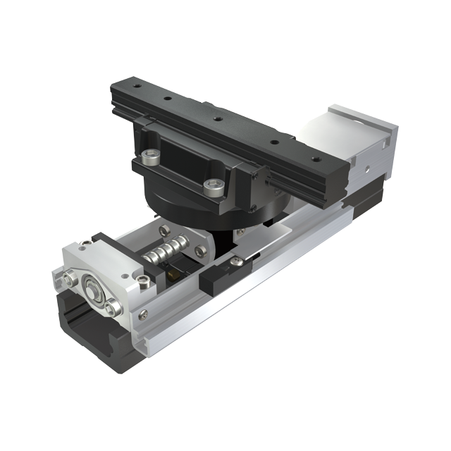
TE86BF(Motor folding back specification)
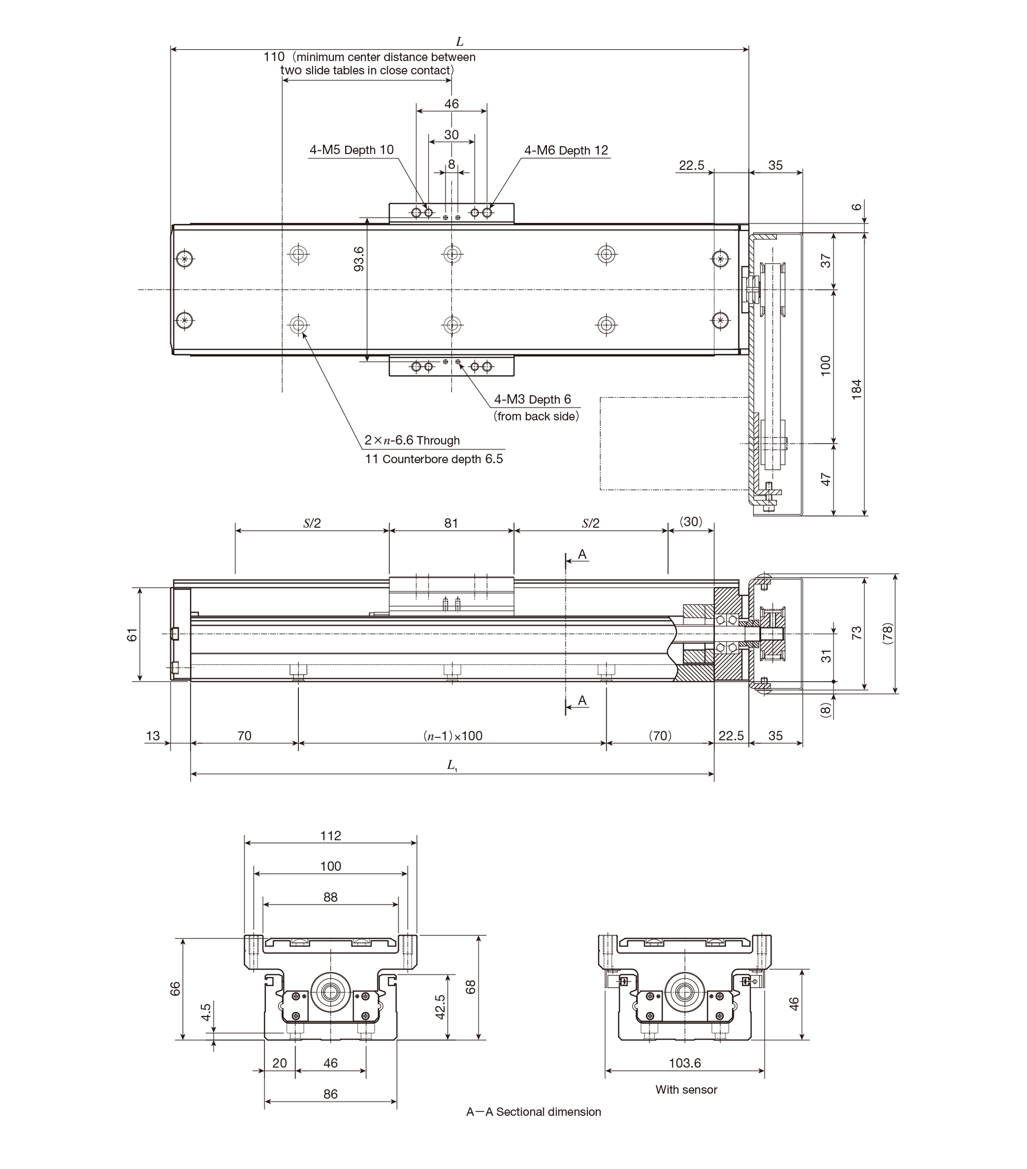
unit: mm
| Bed length L1 |
Overall length L |
Stroke length S(1) |
Mounting holes of bed n |
Mass(Ref.) Kg(2) |
|---|---|---|---|---|
| 340 | 375.5 | 200(90) | 3 | 4.6 |
| 440 | 475.5 | 300(190) | 4 | 5.2 |
| 540 | 575.5 | 400(290) | 5 | 5.8 |
| 640 | 675.5 | 500(390) | 6 | 6.4 |
| 740 | 775.5 | 600(490) | 7 | 7.0 |
| 840 | 875.5 | 700(590) | 8 | 7.6 |
| 940 | 975.5 | 800(690) | 9 | 8.1 |
| Notes(1) | The value indicates the allowable stroke when limit sensors are mounted. The value in ( ) represents dimension for two slide tables in close contact. |
| (2) | The value shows the mass of the entire table with one slide table, and it is 0.6kg heavier with two slide tables. |
| Remarks |
|
Some products are not shown in the catalogue. Also, modifications can be made to meet your requirements. Please do not hesitate to make inquiries.